


The LAN is the networking infrastructure that provides access to network communication services and resources for end users and devices spread over a single floor or building. You create a campus network by interconnecting a group of LANs that are spread over a small geographic area. Campus network design concepts are inclusive small networks that use a single LAN switch, up to very large networks with thousands of connections.
The campus wired LAN enables communications between devices in a building or group of buildings, as well as interconnection to the WAN and Internet edge at the network core.

The campus wired LAN uses a hierarchical design model to break the design up into modular groups or layers. Breaking the design up into layers allows each layer to implement specific functions, which simplifies the network design and therefore the deployment and management of the network.
Modularity in network design allows you to create design elements that can be replicated throughout the network. Replication provides an easy way to scale the network as well as a consistent deployment method.
In flat or meshed network architectures, changes tend to affect a large number of systems. Hierarchical design helps constrain operational changes to a subset of the network, which makes it easy to manage as well as improve resiliency. Modular structuring of the network into small, easy-to-understand elements also facilitates resiliency via improved fault isolation.
includes the following three layers:

Provides endpoints and
users direct access to the
network

Aggregates access layers
and provides connectivity to
services

Provides connectivity between
distribution layers for large LAN
environments
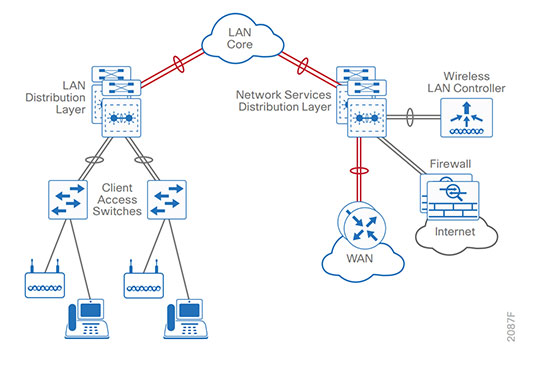
Figure1. LAN hierarchical design
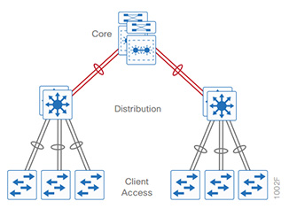
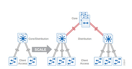
Figure2. Scalability by using a modular design
Each layer—access, distribution, and core—provides different functionality and capability to the network. Depending on the characteristics of the deployment site, you might need one, two, or all three of the layers.
For example, a site that occupies a single building might only require the access and distribution layers, while a campus of multiple buildings will most likely require all three layers.
Regardless of how many layers are implemented at a location, the modularity of this design ensures that each layer will provide the same services, and in this architecture, will use the same design methods.
The access layer is where user-controlled devices, user-accessible devices, and other end-point devices are connected to the network. The access layer provides both wired and wireless connectivity and contains features and services that ensure security and resiliency for the entire network.
Figure3. Access layer connectivity
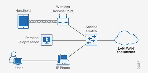
Device connectivity —The access layer provides high-bandwidth device connectivity. To help make the network a transparent part of an end-user’s day-to-day job, the access layer must support bursts of high-bandwidth traffic when users perform routine tasks, such as sending large emails or opening a file from an internal web page. Because many types of end-user devices connect at the access layer—personal computers, IP phones, wireless APs, and IP video surveillance cameras—the access layer can support many logical networks, delivering benefits for performance, management, and security.
Resiliency and security services —The access-layer design must ensure that the network is available for all users who need it, whenever they need it. As the connection point between the network and client devices, the access layer must help protect the network from human error and from malicious attacks. This protection includes ensuring that users have access only to authorized services, preventing end-user devices from taking over the role of other devices on the network, and, when possible, verifying that each end-user device is allowed on the network.
Advanced technology capabilities —The access layer provides a set of network services that support advanced technologies, such as voice and video. The access layer must provide specialized access for devices using advanced technologies, to ensure that traffic from these devices is not impaired by traffic from other devices and also to ensure efficient delivery of traffic that is needed by many devices in the network.
The preferred options for the campus wired LAN include the following Cisco switches as access-layer platforms:
 Cisco Catalyst
3850 Series Switches
 Cisco Catalyst
3650 Series Switches
 Cisco Catalyst
4500E Series Switches
 Cisco Catalyst 2960-X and
2960-XR Series Switches
The distribution layer supports many important services. In a network where connectivity needs to traverse the LAN end-to-end, whether between different access layer devices or from an access layer device to the WAN, the distribution layer facilitates this connectivity.
Scalability —At any site with more than two or three access-layer devices, it is impractical to interconnect all access switches. The distribution layer serves as an aggregation point for multiple access-layer switches. The distribution layer can lower operating costs by making the network more efficient, by requiring less memory, by creating fault domains that compartmentalize failures or network changes, and by processing resources for devices elsewhere in the network. The distribution layer also increases network availability by containing failures to smaller domains.
Reduce complexity and increase resiliency —The campus wired LAN has the option to use a simplified distribution layer, in which a distribution-layer node consists of a single logical entity that can be implemented using a pair of physically separate switches operating as one device or using a physical stack of switches operating as one device. Resiliency is provided by physically redundant components like power supplies, supervisors, and modules, as well as stateful switchover to redundant logical control planes.
This approach reduces complexity of configuring and operating the distribution layer because fewer protocols are required. Little or no tuning is needed to provide near-second or sub-second convergence around failures or disruptions.
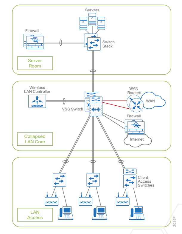
The distribution layer provides connectivity to network-based services, to the WAN, and to the Internet edge. Network-based services can include and are not limited to Wide Area Application Services (WAAS) and WLAN controllers. Depending on the size of the LAN, these services and the interconnection to the WAN and Internet edge may reside on a distribution layer switch that also aggregates the LAN access-layer connectivity. This is also referred to as a collapsed core design because the distribution serves as the Layer 3 aggregation layer for all devices.
Figure4. Two-tier design: Distribution layer functioning as a collapsed core
Larger LAN designs require a dedicated distribution layer for network-based services versus sharing connectivity with access layer devices. As the density of WAN routers, WAAS controllers, Internet edge devices, and WLAN controllers grows, the ability to connect to a single distribution layer switch becomes hard to manage. There are a number of factors that drive LAN design with multiple distribution layer modules:
The number of ports and port bandwidth that the distribution layer platform can provide affects network performance and throughput.
Network resilience is a factor when all LAN and network-based services rely on a single platform, regardless of that platform’s design, it can present a single point of failure or an unacceptably large failure domain.
Change control and frequency affects resilience. When all LAN, WAN, and other network services are consolidated on a single distribution layer, operational or configuration errors can affect all network operation.
Geographic dispersion of the LAN access switches across many buildings in a larger campus facility would require more fiber optic interconnects back to a single collapsed core.
Like the access layer, the distribution layer also provides quality of service (QoS) for application flows to guarantee critical applications and multimedia applications perform as designed
The preferred Cisco switches for deploying the distribution layer of the campus wired LAN include:
In a large LAN environment, there often arises a need to have multiple distribution layer switches. One reason for this is that when access layer switches are located in multiple geographically dispersed buildings, you can save potentially costly fiber-optic runs between buildings by locating a distribution layer switch in each of those buildings. As networks grow beyond three distribution layers in a single location, organizations should use a core layer to optimize the design.
Another reason to use multiple distribution layer switches is when the number of access layer switches connecting to a single distribution layer exceeds the performance goals of the network designer. In a modular and scalable design, you can collocate distribution layers for data center, WAN connectivity, or Internet edge services.
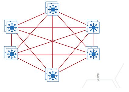
In environments where multiple distribution layer switches exist in close proximity and where fiber optics provide the ability for high-bandwidth interconnect, a core layer reduces the network complexity, from N * (N-1) to N links for N distributions, as shown in the following two figures.
Figure6. LAN topology with a core layer
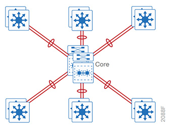
Figure7. LAN topology without a core layer
The core layer of the LAN is a critical part of the scalable network, and yet it is one of the simplest by design. The distribution layer provides the fault and control domains, and the core represents the 24x7x365 nonstop connectivity between them, which organizations must have in the modern business environment where connectivity to resources to conduct business is critical. Connectivity to and from the core is Layer 3–only, which drives increased resiliency and stability.
The preferred Cisco switches used as campus core-layer platforms are:

Cisco Nexus 7700 Series Switches with Supervisor 2E
Cisco Catalyst 6807-XL Switches with Cisco Catalyst 6500 Supervisor Engine 6T
The capacity, density, and features are the primary differences driving platform selection. Both lead platforms have sibling platforms that may be appropriate for the core role in existing networks or networks where the full capabilities of the lead platforms are not required.
When you scale from a single switch in a campus LAN up to a full three-tier campus network, the reliability of the network is increasingly important, because network downtime likely affects a greater user population with a larger workplace and economic significance. To mitigate the concerns about unavailability of network resources, campus designs include additional resiliency options, such as redundant links, switches, and switch components. In traditional multilayer campus designs, the added resiliency comes at a cost of configuration complexity, with most of the complexity introduced from the interaction of the access and aggregation layers of the campus LAN.
The primary function of the distribution layer is to aggregate access layer switches in a given building or campus. The distribution layer provides a boundary between the Layer 2 domain of the access layer and the Layer 3 domain that provides a path to the rest of the network. This boundary provides two key functions for the LAN. On the Layer 2 side, the distribution layer creates a boundary for spanning tree protocol (STP), limiting propagation of Layer 2 faults. On the Layer 3 side, the distribution layer provides a logical point to summarize IP routing information when it enters the network. The summarization reduces IP route tables for easier troubleshooting and reduces protocol overhead for faster recovery from failures.
Traditional LAN designs use a multi-tier approach with Layer 2 from the access layer to the distribution layer, where the Layer 3 boundary exists. The connectivity from the access layer to the distribution layer can result in either a loop-free or looped design.
In the traditional network design, the distribution layer has two standalone switches for resiliency. It is recommended that you restrict a Layer 2 virtual LAN (VLAN) to a single wiring closet or access uplink pair in order to reduce or eliminate topology loops that STP must block and that are a common point of failure in LANs. Restricting a VLAN to a single switch provides a loop-free design, but it does limit network flexibility.
To create a resilient IP gateway for VLANs in the traditional design, you must use first-hop redundancy protocols, which provide hosts with a consistent MAC address and gateway IP for a VLAN. Hot standby routing protocol (HSRP) and virtual router redundancy protocol (VRRP) are the most common gateway redundancy protocols, but they only allow hosts to send data out one of the access uplinks to the distribution layer and require additional configuration for each aggregation switch in order to allow you to distribute VLANs across uplinks. Gateway loadbalancing protocol (GLBP) does provide greater uplink utilization for traffic exiting the access layer by balancing load from hosts across multiple uplinks, but you can only use it in a non-looped topology.
All of these redundancy protocols require that you fine-tune the default timer settings in order to allow for subsecond network convergence, which can impact switch CPU resources.
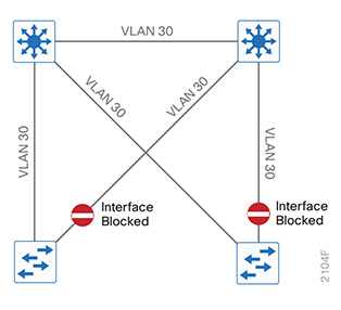
Some organizations require the same Layer 2 VLAN be extended to multiple access layer closets to accommodate an application or service. The looped design causes spanning tree to block links, which reduces the bandwidth from the rest of the network and can cause slower network convergence. The inefficiencies and the increased potential for misconfiguration drive network engineers to look for more appealing alternatives.
Figure8. Traditional loop-free design with a VLAN per access switch
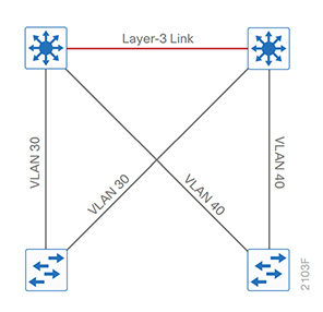
Figure9. Traditional looped design with VLANs spanning access switches
In another approach to access and distribution layer design, you can use Layer 3 all the way to the access layer. The benefits of this design are that you eliminate spanning tree loops and reduce protocols because the IP gateway is now the access switch. Because there are no spanning-tree blocking links, you can use both uplinks to the access layer and increase effective bandwidth available to the users.
The challenge with the routed access layer design is that the Layer 2 domains are confined to a single access closet, which limits flexibility for applications that require Layer 2 connectivity that extends across multiple access closets.
You can overcome the Layer 2 limitations of the routed access layer design by adding campus fabric capability to the Layer 3 access network. The campus fabric design enables the use of virtual networks (overlay networks) running on a physical network (underlay network) in order to create alternative topologies to connect devices. In addition to network virtualization, campus fabric allows for software-defined segmentation and policy enforcement based on user identity and group membership, integrated with Cisco TrustSec technology. For additional information, visit cisco.com and search for “Campus Fabric.”
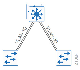
An alternative that can handle Layer 2 access requirements and avoid the complexity of the traditional multilayer campus is called a simplified distribution layer design. The design uses multiple physical switches that act as a single logical switch, such as switch stack or a VSS, or the less preferred single, highly-redundant physical switch. One advantage of this design is that spanning tree dependence is minimized, and all uplinks from the access layer to the distribution are active and passing traffic. Even in the distributed VLAN design, you eliminate spanning tree blocked links because of looped topologies. You reduce dependence on spanning tree by using EtherChannel to the access layer with dual-homed uplinks. This is a key characteristic of this design, and you can load-balance up to eight links if needed for additional bandwidth. At the same time, multiple links in an EtherChannel have better performance characteristics versus single independent links.
Figure10. Simplified distribution design with a VLAN per access switch
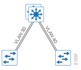
Figure11. Simplified distribution design with VLANs spanning access switches
EtherChannel is a logical interface that can use a control plane protocol to manage the physical members of the bundle. It is better to run a channel protocol instead of using forced-on mode because a channel protocol performs consistency checks for interfaces programmed to be in the channel and provides protection to the system from inconsistent configurations. Cisco Catalyst switches provide both port aggregation protocol (PAgP), which is a widely deployed Cisco designed protocol, and link aggregation protocol (LACP), which is based on IEEE 802.3ad.
There are several other advantages to the simplified distribution layer design. You no longer need IP gateway redundancy protocols such as HSRP, VRRP, and GLBP, because the default IP gateway is now on a single logical interface and resiliency is provided by the distribution layer switch or switches. Also, the network will converge faster now that it is not depending on spanning tree to unblock links when a failure occurs, because EtherChannel provides fast sub-second failover between links in an uplink bundle.
The topology of the network from the distribution layer to the access layer is logically a hub-and-spoke topology, which reduces complexity of design and troubleshooting. The hub-and-spoke topology design provides a more efficient operation for IP Multicast in the distribution layer because there is now a single logical designated router to forward IP Multicast packets to a given VLAN in the access layer.
Finally, by using the single logical distribution layer design, there are fewer boxes to manage, which reduces the amount of time spent on ongoing provisioning and maintenance.
Find more solutions and expert guidance before, during, and after your tech deployments: Security Migration Options; Security Solution-NGFWs; FTTx Solutions
If you need detailed solutions for your deployments and network, you can:
Email Us:daqintech@aliyun.com